- Welcome to Victor Zheng's Website/
- Articles/
- Technology/
- Testing ESP32-C3 XIAO Bluetooth and WiFi module/
Testing ESP32-C3 XIAO Bluetooth and WiFi module

Table of Contents
In my current CSC490 course, we are working with some pretty interesting technologies and testing various sensors. One of them is the ESP32-C3, which is dubbed “A cost-effective RISC-V MCU with Wi-Fi and Bluetooth 5 (LE) connectivity for secure IoT applications”. Here I’ll discuss why we are choosing it for our final project in this course and our findings. My professor gave me the ESP32-C3 for testing purposes as we are working on a chess project for our final assignment which may require bluetooth and WiFi module capabilities.
The Class #
The class itself is a Capstone Design Project course where in the first 5 weeks we learn how to design a computer science project and then in the second half of the course we pick a project and actually implement it.
Our first weeks of lectures have introduced us to the Arduino ecosystem, AT Mega328P, peripherals, IoT, 3D-printing, PCBs, and much more. We also got to keep our own Grove Beginner Kit for Arduino which is a pretty good starter kit. I also had a sensor kit at home which this kit can easily hook up to for running different simulations and tests.
ESP32-C3 Capabilities #
From the ESP32-C3 website:
ESP32-C3 is a single-core Wi-Fi and Bluetooth 5 (LE) microcontroller SoC, based on the open-source RISC-V architecture. It strikes the right balance of power, I/O capabilities and security, thus offering the optimal cost-effective solution for connected devices. The availability of Wi-Fi and Bluetooth 5 (LE) connectivity not only makes the device's configuration easy, but it also facilitates a variety of use-cases based on dual connectivity.
The main benefit for our project is the Wi-Fi and Bluetooth 5 (LE) capabilities. Usually no single chip has this functionality out of the box where you can plug-and-play without using additional hardware and peripherals. For rapid-prototyping, this is excellent.
I’m also currently taking CSC368, so learning/using a RISC-V architecture is quite relevant. One advantage is the clock cycle frequency of 160 MHz compared to just 20MHz maximum on the ATMega328P, which is what the Arduino Uno/Nano line is built on.
What I also really appreciate is that it comes with 400KB of SRAM and 4MB of on-board flash memory, which compared to 2 KB SRAM and 32 KB flash on the ATMega328P is a huge improvement.
Plus, the major difference in the processor is crazy. We have an 8-bit processor vs a 32-bit RISC-V processor. The list goes on as well. Probably due in part due to the newer release sometime in 2020 for the ESP32-C3 whereas the ATMega328 came out in 2005. With Moore’s Law, we’re able to fit more transistors on the same amount of area. Therefore, we can expect performance to be exponentially better.

Disadvantages #
ESP32-C3 integrates a 32-bit core RISC-V microcontroller with a maximum clock speed of 160 MHz. With 22 configurable GPIOs, 400 KB of internal RAM and low-power-mode support, it can facilitate many different use-cases involving connected devices. The MCU comes in multiple variants with integrated and external flash availability. The high-temperature support makes it ideal for industrial and lighting use-cases.
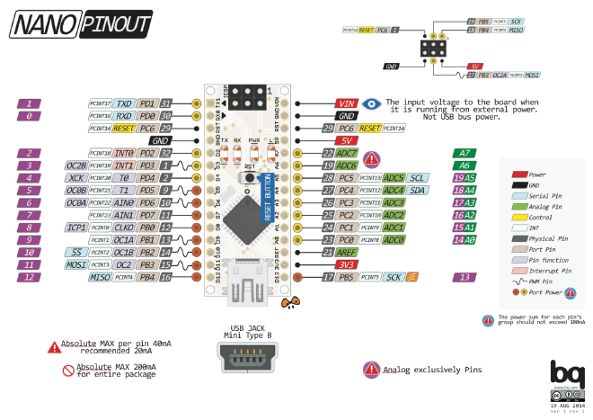
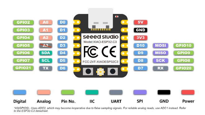
In theory, we have 22 GPIOs, but with the XIAO version, we only have 11 digital I/O ports. I’m not entirely sure why they reduced the number of GPIOs, which is somewhat disappointing. My hypothesis is that they wanted to make the form factor small, and they needed space for their built-in antenna and SPI interface. When we look at the Arduino Nano, there are over 20 GPIO pins that we can use. For our final chess project, we need a good number of GPIO ports to control LEDs and read inputs. The Arduino Nano’s substantial pinout offers a significant advantage compared to the 11 pins on the XIAO ESP32-C3.

Testing the Bluetooth Range #
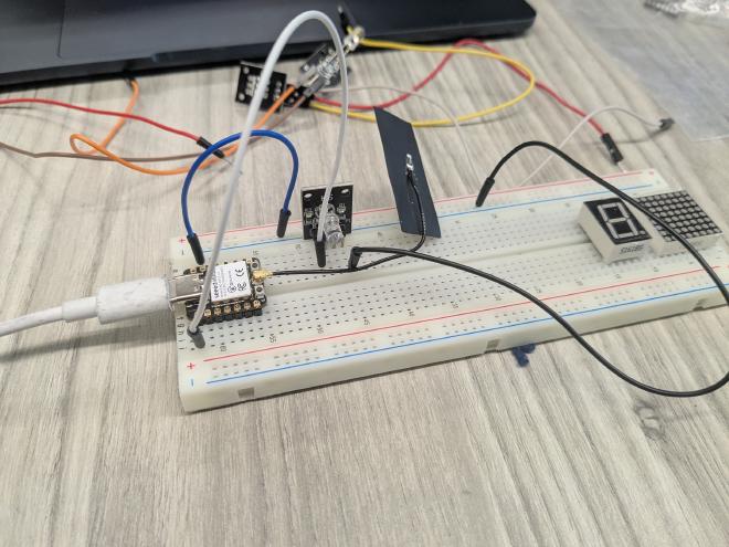
What’s convenient about the XIAO module is that it comes with the antenna built in. All I needed to do was plug and play. The Arduino-ESP32 library includes built-in examples of how to run bluetooth simulations. Details about their GitHub repository are available here.
 |
|---|
| The ESP32-C3 XIAO module pinout |
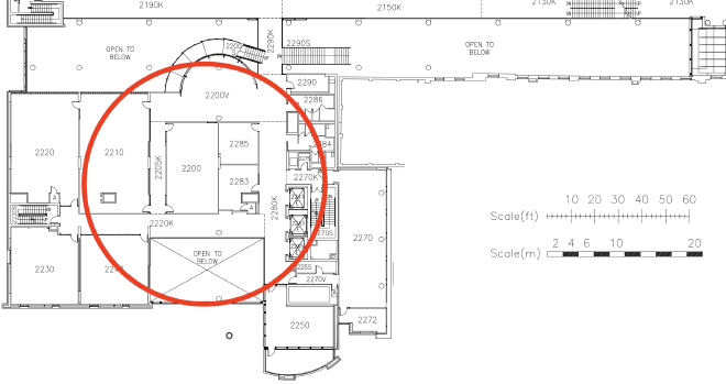
For testing purposes, I ran a quick bluetooth test from BA2240, an undergraduate lab room. Not surprisingly, Bluetooth Low Energy (BLE) version 5 maintained connectivity approximately 30 meters from the room. For this particular test, I installed an app called LightBlue, which is the industry standard for quick BLE testing.
I walked 10 steps at a time and ran the test, finding that it performed extremely consistently. The connection began to falter when it reached room 2286 (men’s washrooms) where the BLE connection dropped.
Overall, this is an excellent product for projects requiring bluetooth connectivity directly from a chip.
The following photo shows the bluetooth range. Interestingly, the bluetooth works approximately 30 meters from my laptop, which at the time I had placed in BA2240.
 |
|---|
| The bluetooth module range from BA2240 |
Testing the Wi-Fi Range #
The second component I tested was the Wi-Fi. The Wi-Fi module quickly detected all available networks and connected to the U of T network successfully. I also tested its ability to function as its own Wi-Fi network that I could connect to with my phone, which worked well. I believe this is called Software Access Point Mode, similar to what TPLink extenders use (which I tested back in high school). We discussed this briefly in my networking course, CSC458 as well.
Conclusion and Next Steps #
I’m currently working on a chess-related sensor project for the final assignment of this course, with more details to be published later.
We are definitely going to use the ESP32-C3 module if we require Bluetooth or Wi-Fi capabilities. It’s a neat little product that I believe will be the beginning of many more great SOCs to come. I predict a revolution in embedded systems with RISC-V architectures on the horizon.
One thing to note however is that the pinouts on the XIAO module are not ideal for connecting a ton of peripherals. Therefore, likely it’d be better to use the chip straight from the manufacturer; the drawback being that I’d need to design the PCB and figure out how to flash the chip correctly.